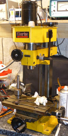
It is a Sieg X1, painted yellow and sold as a Clarke CMD10 in this case.
These are basic machines built to a price and tend to be rather roughly finished in the places that don’t show (and some that do).
Much as it was apparently loved by its previous owner, Day 1 was spent un-seizing and lubricating parts – particularly the bed, and getting the leadscrews to move reasonably (it would take a lot of careful fettling to get it to move really nicely – some folk have the knowledge, skill and time, and have done it).
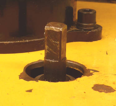 Drawbar cover missing – hence swarf inside the gear casing
Day2 was the big switch-on, and it ran immediately, as soon as I plugged it in – Problem 1: no proper ‘no-volt release’ – dangerous.
Problem 2 was that the speed controller did not control the speed – it just ran at one constant speed.
Deep breath – the controllers in Sieg machines are notoriously fragile and expensive (£185…).
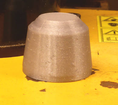 Drawbar cover 3d printed, swarf vacuumed out
Web searching revealed some circuit diagrams that kind folk had reverse-engineered and posted – not of my board, but related boards in other Sieg machines.
Apart from early thyristor versions, they are all mosfet choppers – the dc motor being supplied with rectified mains (no link capacitor) chopped by a mosfet.
When they break, it is almost always the mosfet – most people blame too much current through the mosfet, but it is an IRFP450 in my 150W machine which can handle 14A cold and 8A hot, plus pulses up to 56A – and the circuit has a current over-load trip built in.
Far more likely, if feel, that its 500V rating is not enough to handle transients on top of the 380V mains peak – at least one other person the the web thinks the same (as it happens, the mosfet in this mill was working).
Taking a deep breath, I started (what I thought was) fault finding – made more tricky because the whole control circuit is at mains live potential – so: battery-powered scope, set-up, stand back, turn on and view – then turn off and repeat.
So that I did not have to probe the live board, I soldered insulated wires to test points. And that was my undoing, as, in swapping the scope probe from one test point to another, a wire pinged back and touched the metal chassis – ‘pop’ went one of the opto-couplers as its package disintegrated (and out when the lights as the RCD tripped).
Fault-finding had turned into fault-adding… Heaven knows what else was ruined as the 240V-driven surge went through all those LM324s on the controller board.
I dejectedly disconnected everything and left the workshop for a lie down.
Oh well…..
A few things:
- I wish I had saved a 100W incandescent bulb from the rush-to-leds, as it would have made a good dummy load
- The board has two ‘off’ switches and a bunch of relay inter-locks that make it hard to fault find, but still no true ‘no-volt release’
- Despite all the op-amps (12 of them) there is no slow-start – you have to remember to turn the speed control to minimum before switching on, or the overload trips (when the board works)
- The motor is voltage regulated to make it fairly constant-speed, and it has current feedback for something – maybe some protection before the trip goes? (there is no diode amongst the op-amps (I can find) to make it a constant current over-ride)
- The mosfet gate drive is quite cunning
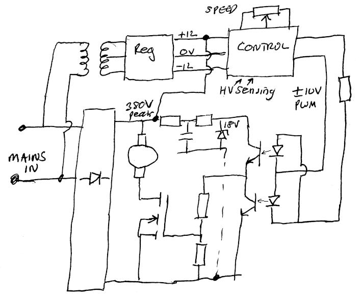 The latter uses a pair of opto-isolators to bring the PWM waveform to the mosfet gate.
The leds are wired back-to-back, so that one or the other is on when they are driven with a bi-polar waveform.
The output transistors are wired as a totem pole drive for the gate (from a local 18V supply), giving the drive reasonably fast turn-on and turn-off – none of the long turn-off tail that a single opto isolator would give.
This is the version in the FC150BJ driver board, intended for 150W 220V dc motors. 250W and 350W versions duplicate the mosfet and the two gate resistors.
The control circuit is tied to the un-filtered rectified 230V rail so that motor current and voltage can be sensed using resistors – Heaven knows why it is tied via +12V and not 0V, nor why a bi-polar supply is required.
It was one of the opto-coupler input ends that I earthed with such disaster.
"machine" - Google News
September 29, 2021 at 05:39PM
https://ift.tt/3zP0wFR
Milling machine speed controller: A frustrating day in the workshop - Electronics Weekly
"machine" - Google News
https://ift.tt/2VUJ7uS
https://ift.tt/2SvsFPt
Bagikan Berita Ini


0 Response to "Milling machine speed controller: A frustrating day in the workshop - Electronics Weekly"
Post a Comment