Machine tool QC is on the cusp of a profound change. According to Steffen Hailer, a product manager and application engineer for AfM Technology in Aalen, Germany, a soon-to-be-issued ISO standard (ISO 230-13) will define the process by which a machine tool can be calibrated such that its probing measurements can be accepted by the quality department.
This doesn’t mean the machine tool will always be as accurate as a typical CMM. But the production and QC departments will be speaking the same language, and the machine measurements will be usable for QC. That, in turn, offers advantages in better process control and a lower cost of quality.

Volumetric error compensation (VEC) is perhaps the most important factor making it possible for a machine tool to perform acceptable QC. But even if you still use off-line equipment for final inspection (which will generally be the case), the latest methods in VEC offer the best route to ensuring high accuracy in producing complex parts.
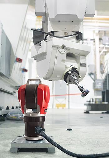
For example, Art Kietlinski, operations manager for Automated Precision Inc. (API) of Rockville, Md., said the company’s compensation package will make a four- to five-fold improvement in the volumetric accuracy of a multi-axis machine tool, and sometimes an even greater improvement. “Typically, we might see a machine with a maximum volumetric error at the tool tip of say 0.3 to 0.5 millimeters before calibration. And then after calibration, we might be around 0.075. On a five-axis machine, we’re looking at and improving all 43 possible errors.” [See “Keeping Machines Honest with Advanced Calibration, Optimization,” Manufacturing Engineering, June 2019, for an explanation of the 43 possible machine tool deviations.]
API does this by combining a laser tracker with what they call their Active Target, explained Ron Hicks, vice president of product management and marketing. “Active Target is a small motorized reflector mounted in the spindle. It allows the laser tracker to accurately measure the machine’s tool tip position from a single instrument position.” That’s significant, Hicks pointed out, because the VEC process moves the spindle in real time through all of the machine’s axes during the measurement process. That wouldn’t be possible with a standard laser tracker reflector, because the beam would be broken at various points throughout the machine’s volume. Hicks added that “unlike conventional laser processes, our system does not have to be aligned to the major axes of a machine tool. This has dramatic advantages in terms of speed and accuracy…We’ve been able to compensate two machines in a single day.”
API’s system measures “all possible machine poses,” added Kietlinski, so in a large machine volume (e.g. 10 m) it might plot as many as 250 points. From there, the proprietary software generates coefficients for the polynomials that calculate the necessary error corrections for each axis. As Kietlinski explained, this is complex math, because “the errors aren’t necessarily linear. You might end up with a second or third order polynomial that must be solved for.”
Northrop Grumman’s plant in Palmdale, Calif., is one of several success stories, said Hicks. The plant uses large five-axis gantry machines to perform all the trim and hole drilling for the entire F-35 fuselage, and API visits each year to perform VEC on each machine. Meanwhile, said Kietlinski, Lockheed Martin and Israeli Aerospace machine the wing sections on horizontals, which API also services.
There are limits. A recent visit to a Michigan company producing high-quality tooling, prototypes, and low-volume production components introduces a cautionary note.
Understanding Limitations
Kietlinski recounted that the Michigan company invited API to demonstrate their equipment on a five-axis machine that had already undergone VEC based on a 21 error map, “which is the norm for most machines and CMMs.” As Kietlinski explained, “all these calibrations assume the machine has a rigid body, which means all the angular errors would be the same throughout that axis’ travel through the volume. So, for example, no matter where I run the X-axis through the volume, if I were to measure pitch, yaw, and roll errors, I’d get the same angular data. But that’s not always the case on these larger machines.” That’s usually due to the rails not being parallel, he said. This creates stress on the machine and its drive system, which causes the “load currents to rise, and a number of other issues.”
So the first thing Kietlinski checked was the straightness of the linear axes, which takes under an hour using the laser tracker. He added that there is usually a direct relationship between straightness and other geometrical errors, like pitch, yaw, roll and squareness errors, “because you can’t even assess squareness if you’re not straight.” In this case, he found errors of up to 200 to 250 microns (0.010”). API performed a full alignment on the machine, “even breaking the bridge loose and squaring it up mechanically. Then we applied the 21 error correction map. At this point…the angular errors were the same across the machine, and we were able to improve the machine tenfold over the previous calibration.”
That’s due largely to the enhanced mechanical alignment, Kietlinski emphasized. “The better you have the machine mechanically aligned, the better the results of the calibration.” Conversely, “you can’t take a machine that isn’t mechanically aligned and try to fix everything with software.”
Correcting for In-Process Errors
Within the limits just discussed, VEC can make a remarkable improvement to a machine’s geometric inaccuracies. But what about “working inaccuracies,” the additional errors that occur during machining, due to operational stresses, thermal instability, and other factors? Bill Malanche, chief operating officer for Mitsui Seiki (USA), Franklin Lakes, N.J., listed the major causes of inaccuracy as “lost motion, heat, and design. Lost motion works itself into many aspects, but it can be summed up by geometric alignment and fit.” With VEC addressing the other factors, thermal instability emerges as perhaps the primary source of in-process errors. And the bigger machine, the more variation one might see in actual versus nominal tool position.

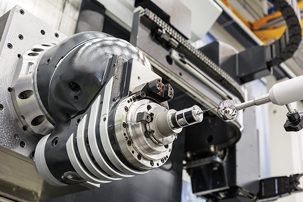
One approach to dealing with this problem is to use a machine’s internal probe to help calculate that deviation, and then compensate for it. Doug Schulte, business development manager for Select Machining Technologies, Windsor, Conn., said their Soraluce machines “probe a qualification sphere in a number of preset points. It does this for many head and axis positions. Software then compares the measured points to the machine’s kinematic model and makes any compensation necessary to ensure the tool center point in the machine’s geometry.” Soraluce calls this function Dynamic Head Calibration (DHC), and Schulte said it’s a common feature in five-axis machines. [Manufacturing Engineering covered Okuma’s version in the June 2019 article.]
Soraluce machines are generally equipped with multiple two-axis heads, and DHC takes 25 to 30 minutes for the entire measurement cycle. It is designed for periodic pre-machining compensation, like VEC. But Soraluce has an added feature called Accura Heads that targets possible in-process errors, and takes only a minute or two to do so. This option uses the same probe and measuring sphere, but runs inside the machining program, explained Schulte.
“If you’re going to address a feature on a part that’s in a specific angle and that angle is very critical, you can use the Accura Heads routine to verify the angle and the tool point position of that particular orientation. Then it will make that offset for that one tool. You do that probe cycle immediately before you run that operation.”
Schulte also indicated that for tighter tolerances in certain machine designs, the user should mount the sphere closer to the area where they’re going to be cutting, depending on the size of the machine. “Soraluce has built machines with longitudinal travel of more than 60 meters,” he added. One can easily imagine that outside influences might cause a deviation between actual and nominal positioning that far out.
The Machining/QC Handshake
Taking a “compensated machine” as a given, operators can consider the possibility of using a machine tool’s probe to perform QC functions. The new ISO 230-13 standard will define the requirements, and will do so in reference to ISO 10360, which is the standard for CMMs. The key specification with which CMMs are judged is their maximum permissible error (MPE) value. An acceptance test would measure seven orientations (four body diagonals, plus one each along X, Y and Z) with either a step gauge or a laser in combination with a measurement sphere. To pass the test, the maximum deviation (E0) must not be greater than the MPE.

As Hailer explained, the new ISO standard defines the acceptance test procedure and the needed values just as clearly for machine tools, but it’s a new concept for machine builders. “At the moment, no machine tool builder knows the size of their MPE. They have to learn the procedure for determining such a value, and then find out what it is. This is one of the services we provide OEMs.” Once a builder has determined this value for a given machine—and it’s verified on site, just like you would for a CMM installation—a user could do a final part inspection on the machine, never putting it on a CMM, and deliver the part to a customer with a report documenting the accuracy of the measurements.
Whether or not a machine tool’s MPE is acceptable for the end user is another question. But it seems likely that higher precision machines will fulfill satisfactory QC for at least some applications. That’s particularly true for very large parts, observed Béat Ries, grinding products manager for Mitsui Seiki. “You pay a lot of money for a large CMM, especially when you want to go to ultra high accuracy. The numbers are astronomical. It seems no one is able to provide an economical solution.”
There’s more, said Ries. Knowing just the MPE of a CMM or machine tool is not enough to satisfy aerospace or automotive standards. That’s because they also “require an uncertainty value next to each measurement or validation done on parts.” So while many people think of the MPE alone as the “accuracy” of a machine, the figure does not capture the measurement variations—and additional inaccuracies—that occur in the real world. For example, Ries, explained, “temperature fluctuations in a shop would produce differing measurements. So if a CMM has an MPE of 1.9 plus L/250 microns, the calculated uncertainty might be 3 microns per meter. If you measure over one meter, the MPE value would suggest you are accurate to within 5.9 microns. But if you add the uncertainty value you’ll see that you are actually measuring to within plus or minus 8.9 microns.”
Splitting the Micron
One shop that takes measurement extremely seriously is the aptly named Precision Grinding Solutions (PGS) in Hamden, Conn. Owner Curt Reed considers it essential that they have a firm grasp on their QC, to include uncertainty measurements, because they grind rotating jet engine parts for big OEMs like Pratt & Whitney, plus Tier 1 and 2 aerospace suppliers. PGS even has a contract to calibrate gauges for several Pratt locations.

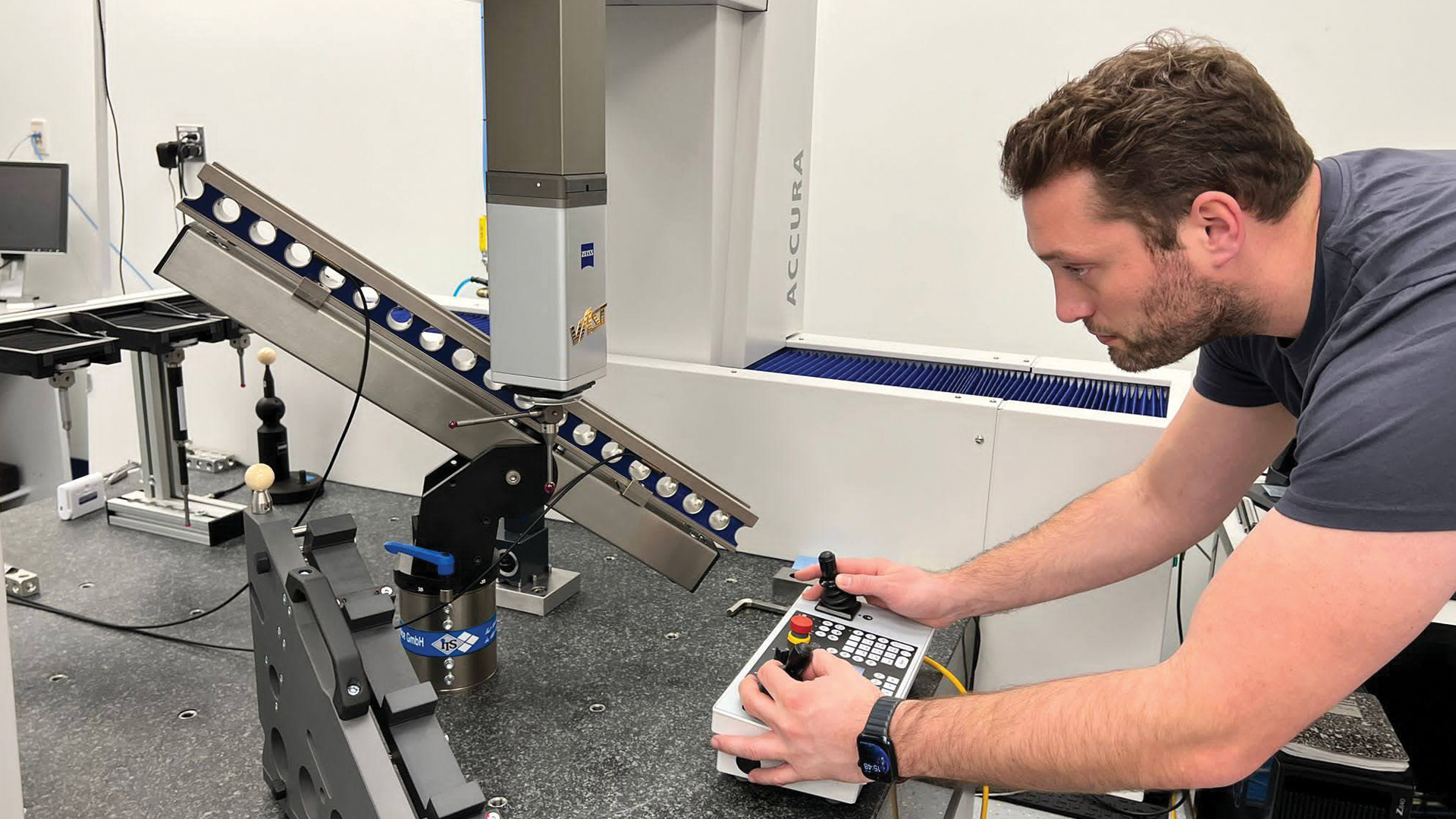
PGS has a Zeiss PRISMO ultra CMM, which Reed refers to as a “reference class” machine. The CMM boasts an E0 of 0.5 + L/500 μm, and PGS has been determining the uncertainty budget “one of the old fashioned ways. You take a known artifact, say one of the Pratt gauges we’re involved in calibrating, and measure a critical feature 50 times or so. Then you examine this spread of data, consider factors like changes in the room’s temperature, plug all that into a long standing formula and come up with an uncertainty figure.”
Now PGS is implementing a new method to get an even better handle on measurement uncertainty: Virtual CMM (VCMM). Reed explained that VCMM is a plugin module for Zeiss’ Calypso executive software package that “enables you to insert another column in your reports that shows the uncertainty of every single measurement you take.” Beyond that, it also captures all the other errors that laser calibration doesn’t account for, added Reed.
PGS is working with AfM to capture the data needed for this effort, which Reed said goes beyond tracking temperature fluctuations and vibrations. “For example, it takes into account whether you’re using a long stylus with a skinny shaft, or a short stubby one. What’s the machine bending signature like? When you’re measuring the machine, what’s the actual geometry, the scales, the guide ways…What does all that look like?” AfM will determine all this by taking a series of special measurements with a set of artifacts that incorporate various balls and steps. Then error files will run in the backgrounds to determine the uncertainty.
In sum, said Reed, “VCMM is a much more modern, more comprehensive way of examining uncertainty for the whole system and the laboratory. It’s not just based on one artifact. It’s qualifying through all the measurements AfM is taking, and it’s qualifying the whole measuring volume of the CMM, not just one local area where you tested a gauge.”
Once finished, Reed commented, the new reports will make the quality picture appear worse, “because it does a better job, feature by feature. If you turn this function on, you’ll see the uncertainty of every single feature being run on every program. So if you measure something that would have been ‘to the micron,’ and you add the uncertainty, maybe it’s 1.15 microns. But it delivers a real, truthful examination of the uncertainty of the whole system.”
Reed’s system is already excellent. PGS has a top-flight CMM and its lab is temperature stable to within one-third of a degree F. But they’ve made other investments to limit uncertainty: “We bought AfM’s software and measuring artifacts to get better control of the machine’s accuracy. We also bought a 700 millimeter step edge identical to the one used by Zeiss service. Our intention is to understand where the machine is at all times.”
PGS will no longer rely solely on annual calibrations from the OEM, as they only represent a snapshot in time. Reed said those visits cost a significant amount of money and still leave one wondering how the machine is performing all year. “If the OEM comes back in a year and the ‘as-found’ calibration is not in spec, it puts every product you’ve been accepting with the machine into question. We’re no longer willing to take that risk. We’re trying to make weekly, or even daily, examinations of our CMMs.”
"machine" - Google News
March 14, 2022 at 07:03PM
https://ift.tt/29CnVlK
A Higher Caliber of Machine Tool QC - SME
"machine" - Google News
https://ift.tt/zEVRZPm
https://ift.tt/8cbLB1f
Bagikan Berita Ini


0 Response to "A Higher Caliber of Machine Tool QC - SME"
Post a Comment